DIY: Helmet Force Air
Winter10
The inside of a race car is hot. The inside of a helmet is hotter. April-October a helmet is like your own personal head-sauna. So I got to thinking that chilled force air might make an interesting project to fill the down time between serial engine replacements.
Self-esteem maintenance requires that we skip all of the ideas
that failed miserably and only show those that worked.
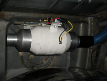
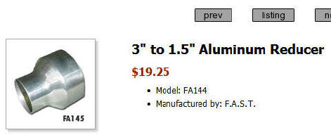
The fan was bought on ebay for $25 or so. Apparently it's a brake duct fan used to keep air flow moving to the rotors when a race car is in the pits. It's plastic and weighs almost nothing. It has 3" ducts. Once you shave off the nubs, they fit the aluminum reducers below nicely.
 It took a while to figure out
a solution for controlling the amount of
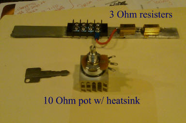
air flow. The first several attempts combined 2X 3 Ohm resisters
with a 10 Ohm
potentiometer. The idea was to allow for the adjustment of the air flow
rate. Slower air is would be cooler, but more air has it's charms
too. The resisters I used were rated at 10 Watts and
the potentiometer 3 Watts. That was the largest potentiometer I could get
for a reasonable price at Mouser. Fastening the resisters to a piece of aluminum
significantly increased the amount of heat that they could dissipate, but the potentiometer was a problem.
It really got warm quickly. Eventually I came up with the idea of JB
Welding a small computer heatsink to it. Getting the heatsink attached well is
important, and it took a couple tries. If the heatsink comes free of the potentiometer because of
repeated shocks on the track, the potentiometer will overheat and fail.
It's anyone's guess if it would fail "open" or "closed", but fuses are your friend.
It took a while to figure out
a solution for controlling the amount of
air flow. The first several attempts combined 2X 3 Ohm resisters
with a 10 Ohm
potentiometer. The idea was to allow for the adjustment of the air flow
rate. Slower air is would be cooler, but more air has it's charms
too. The resisters I used were rated at 10 Watts and
the potentiometer 3 Watts. That was the largest potentiometer I could get
for a reasonable price at Mouser. Fastening the resisters to a piece of aluminum
significantly increased the amount of heat that they could dissipate, but the potentiometer was a problem.
It really got warm quickly. Eventually I came up with the idea of JB
Welding a small computer heatsink to it. Getting the heatsink attached well is
important, and it took a couple tries. If the heatsink comes free of the potentiometer because of
repeated shocks on the track, the potentiometer will overheat and fail.
It's anyone's guess if it would fail "open" or "closed", but fuses are your friend.
Ultimately the various ideas for fastening the heatsink to the potentiometer all proved inadequate to the task. So the potentiometer got pulled out, as did one of the 3 Ohm resisters. A 10 Ohm, 10W resister when in. So the system went from 6-16 Ohms adjustable, to 13 Ohms fixed.
Fixed meaning not adjustable and fixed also meaning the idea worked.
 Cooling
the air flow. The commercial products that I've seen are designed more for
looks then function. The trick with cooling air is to slow it down and
provide lots of heat exchange surface area. An ideal solution would be a big pipe with
lots of cooling fins inside of it. But the commercial versions I've seen
have cooling
fins on the outside. Ice water doesn't need any help cooling the pipe, so
the outside of the pipe doesn't need the fins. But the external fins look
cool and that's good, right?
Cooling
the air flow. The commercial products that I've seen are designed more for
looks then function. The trick with cooling air is to slow it down and
provide lots of heat exchange surface area. An ideal solution would be a big pipe with
lots of cooling fins inside of it. But the commercial versions I've seen
have cooling
fins on the outside. Ice water doesn't need any help cooling the pipe, so
the outside of the pipe doesn't need the fins. But the external fins look
cool and that's good, right?
Worry about surface area inside the pipe, not outside.
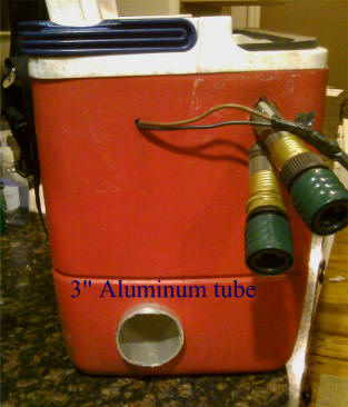
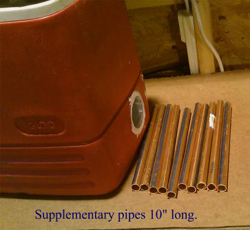
I got the tubing from RacerPartsSolutions, a good place for the odds and ends needed for your latest project whatever it might be.. I bought several sizes, settled with 2.5" and drilled holes in my coolshirt cooler. The pic says 3", but it's really 2.5".
Side note. The green connectors in the picture are garden hose quick connects. I had reliability problems with my coolshirt disconnects a couple yrs ago so I replaced the connectors at the cooler end. That way instead of 4 reasons why cold water isn't flowing as I'm sitting on the grid baking, I've only 2 reasons.....The connectors at the shirt. And those I can fiddle with in the seconds before the pace car heads out.
Sealing the pipe in the cooler. The scheme that ultimately worked was a pair of switch plates and some marine sealant (from Home Depot) that can cure in the absence of air. I found that silicon based sealants wouldn't cure inside of the switch plate because no air was getting to it. The marine sealant required a week of curing time.
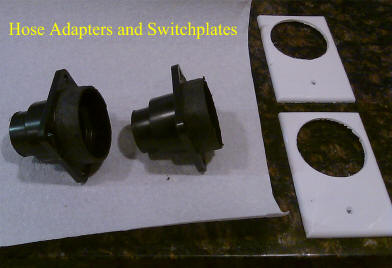

The hose adapters above came from Home Depot. They step down to smaller diameters so you just cut off what you don't need. They are a soft rubber and can be trimmed down to fit inside of the 2.5" aluminum pipe. If they are a tight fit, push both of them in at either end of the pipe at the same time. That way pressing the rubber hose adapter into the pipe won't encourage the pipe to exit the cooler. Which will cost you a week's curing time to try again.
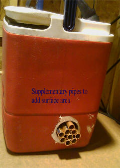
Increasing the surface area inside of the pipe. I dreamed up and discarded a lot of ideas for this. I needed lots of surface area, but whatever I shoved into the pipe also needed lots of contact area with the pipe's inside wall. And it needed to be something that wouldn't rust, and wouldn't impede air flow. The solution that worked was to insert smaller pipes into the larger one with a little epoxy to hold everything in place.
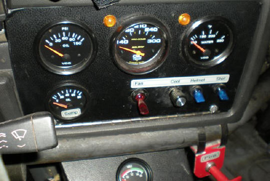
Here's the On/Off switch "Helmet" and the potentiometer "Cool" that controls fan speed. The other switches are for radiator fan, and coolshirt cooler sump-pump.
I cut a whole in the rear firewall for the air hoses, a point I bring up only to mention this make-your-own-custom-grommet-stuff. If you ever need to line the sharp edges of a hole in sheetmetal, use this: https://www.pegasusautoracing.com/productselection.asp?Product=4346 The 1/16th inch size fits perfectly.
The air hose also came from Home Depot. It's generic 1.5" ribbed plastic hose that folks probably use for swimming pools or something. There is a black rubber sleeve in the picture of the blower (top) that connects the hose to the aluminum reducer. Wherever you buy the reducer probably has those sleeves too.